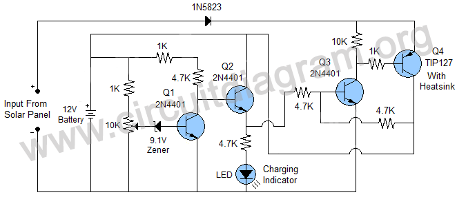
charging and goes off when the charging is completed.
A 12V battery is shown in the schematic but the circuit can easily be adjusted to charge different voltage batteries, this can be done by disconnecting the battery from the circuit and connecting an adjustable power supply with 15V output in the place of battery for temporary basis, then adjust the 10K variable resistor until the charge indicator LED goes off. The same procedure can be applied for other voltage batteries, but it requires knowing the full charge voltage of the battery that is usually written on the batteries or in their specs. As described above for a 12V battery we set the output of adjustable power supply on 15V because a 12V lead acid and SLA battery gets completely charged when it shows 15V on DMM during charging and a 6V battery completely charged when it shows 7.2V on DMM during charging, so for charging 6V battery you have to set 7.2V on the adjustable power supply.
Note: The circuit is able to supply max 5A to the battery.


Copyright 2017 © CircuitDiagram.Org. All rights reserved.
This is a project of a simple transistor based solar battery charger with auto cut off function that will charge a battery from solar panel and disconnect it when it gets full charged. The circuit is based on four transistors and few other passive components. A charge indicator LED will indicate if the battery is
Hello Readers, We frequently add new circuit diagrams, so do not forget to come back often. Thank you.
Sponsored Links
