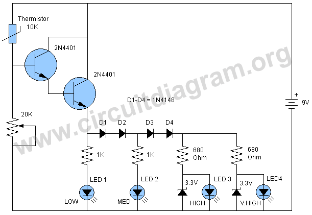
You can also match the LED levels by a thermometer and write the number of centigrade or Fahrenheit with each LED.
By adjusting the 20K variable resistor you can match the circuit with your desire temperature level. For more accurate matching you can also experiment with other higher values thermistor like 100K, 500K or 1000K (1Meg) and also with higher values of variable resistor like 50K, 100K and 200K. You can also use a 3 volt piezo buzzer as sound indication in the place of LED 4.
For best results use same color and brand LEDs with same manufacturer because there is always some difference between LEDs from different manufacturers due to which they will not provide equal brightness on same current and hence the circuit will not provide accurate results. I have used 4 transparent green LEDs and they worked nicely.


Copyright 2013 © CircuitDiagram.Org. All rights reserved.
Here is a very easy and useful schematic of a temperature sensor LED meter circuit. The circuit can be used to sense high and low temperature levels and shows visual indications by lighting up the LEDs. The circuit is using four LEDs marked low, medium, high and very high temperature levels.
Sponsored Links
