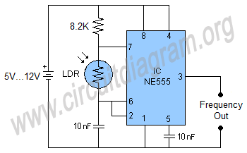
TSL235R, TSL235R is a ready made light to frequency converter available in the market. However, a simple light to frequency converter circuit can also be made by using a 555 timer IC, one LDR and few other passive components as shown in the figure below.
The output frequency of the 555 IC is directly proportional to the light received by the LDR, therefore when there is not much light on the surface of the LDR or the LDR will be placed in the darkness the internal resistance of the LDR will increase and as a result the output frequency of the 555 IC will decrease, and in the opposite condition when light falls on the surface of the LDR its internal resistance decreases due to which the output frequency of the 555 will increase. However, different frequency spectrum can be selected by simply changing the values of 8.2K resistor and 10nF capacitor between pin 6 and negative rail of the supply. The output of the circuit can also be fed to a digital or microcontroller circuit to further enhance and process the signal, a photodiode can also be used in the place of LDR.


Copyright 2017 © CircuitDiagram.Org. All rights reserved.
Converting signals to frequency is a method used in many electronics applications to better process an incoming signal. There are also different devices available in market which can be used to perform this function for example to convert light in to a frequency signal we use
Hello Readers, We frequently add new circuit diagrams, so do not forget to come back often. Thank you.
Sponsored Links
