days, like in TV, DVD and many other appliances. Apart from these appliances they are also used in movement detectors, IR sensing water taps, hand dryers, robots, vehicles etc.
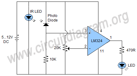
Every IR sensor is consisting of three main things in its circuit, which are IR transmitting LED, Photo diode to receive the IR signal and the signal amplification circuit. The circuit shown here is also consist these three things. The circuit can be used as an obstacle detector by placing both the IR transmitter LED and photodiode side by side. When an obstacle comes infront or them the IR rays reflect through that obstacle and received by the photodiode due to which the output 1 of the LM324 goes high and the LED will become activated.
IR sensors are actually consisted of an infrared transmitter LED and a photo diode. The IR LED continuously emits the infrared signals that can be detected by the photodiode. There are two procedures from which the infrared signals can be detected one is directly or in front of each other and second is by reflection.


Copyright 2016 © CircuitDiagram.Org. All rights reserved.
The figure below shows a project of a simple IR sensor circuit using LM324 IC. The circuit will show visual indication by activated an LED when any object is placed infront of the IR LED and photodiode.
IR sensors (Infrared sensors) are used in many electronic devices now
Hello Readers, We frequently add new circuit diagrams, so do not forget to come back often. Thank you.
Sponsored Links
